The Return of Commodore 64
The Return of the Legend
No, I am not joking. This legendary piece of hardware was so significant back in the 80s that it has been resurrected in the year 2025. I am not going to talk about the project and history behind it. If you are curious to find out more, visit the vendor page.
 Commodore 64 (image credit: Wikipedia)
If you have no idea what the C64 is, you can still find the value in this article. I am going to explain how you work on the bare metal level and even write a small game in the assembly language. The architecture is simple enough, but it has everything we need to explain the logic.
This gave me a great excuse to revisit the bad old days of programming where each byte counted. One could argue that it is the same today, but we all know that’s not true just by the fact that we accepted JavaScript as the new normal. Luckily for most of us, today’s commodity hardware can sometimes handle our written nonsense, and we can afford to trade extra megabytes for faster delivery and readability.
However, if we go down to the bare metal, we cannot afford this. We need efficient code and smart utilization of every byte we have. Each CPU instruction, such as loops or jumps, requires CPU time, meaning that if we are not careful with our limited resources, we can end up with inefficient code, or even be unable to execute the program. Not to mention the reliability of the code, so we don’t crash at every developer nonsense (looking at you Windows!) if we are developing something very significant like an operating system.
Let’s get our hands dirty and honor the past by learning how it was done back then, and what it means today.
Commodore 64 Architecture
Diagram below represents Von Neumann style architecture of the Commodore 64. We will focus on CPU and mostly on registers so we understand how to work with it. As I mentioned before, we are lucky that the architecture is simple enough that all key parts can fit on a diagram. Small, but powerful, as we will about to see.
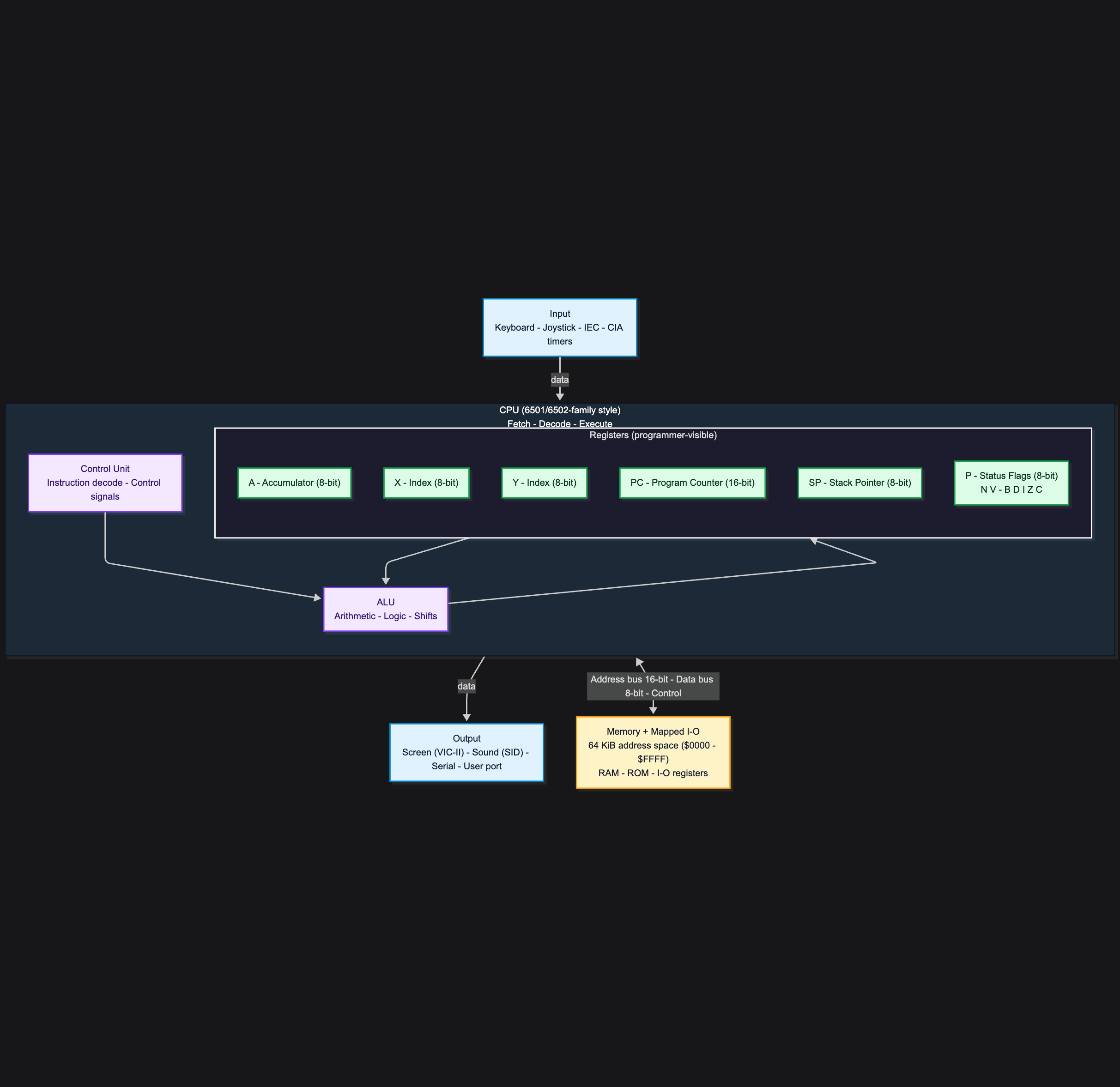 Von Neumann Style Commodore 64 architecture
Registers are small amounts of high speed memory. contained within the CPU. They are used by the processor to store small amounts of data that are needed during processing, such as: the address of the next instruction to be executed.
C64 CPU Registers
For now, don’t worry about code or programming, as we need to understand the machine’s logic and components first.
The Commodore 64 runs on the 6510/8500 processors. These processors expose six registers to the developer. Each one serves a different purpose, so let’s introduce their roles.
“A” is the accumulator register. This is where we keep intermediate values and variables, load values for processing, and perform most arithmetic and logic operations.
“X” and “Y” are index registers. They are used for indexing, counters, and offsets. Think of them as support registers that help you work efficiently with memory, often alongside “A”.
“P” is the status/flags register.
“PC” is the program counter.
“SP” is the stack pointer.
One more important concept is the “BUS”. This is not a register. It is the “glue” between components. More precisely, it is the set of internal connections used to transfer addresses, data, and control signals between the CPU, memory, and I/O.
Program Counter (16-bit register)
This is where the magic happens.
While most registers are 8-bit, the program counter (PC) is the exception. Its purpose is to hold the address of the next instruction to execute.
If we imagine memory as a set of small boxes where each box has its own number (we typically use hexadecimal to keep addresses compact), then a 16-bit PC can represent 65,536 different addresses, from $0000 to $FFFF. Since each address points to a single 8-bit byte, that gives a total of 65,536 bytes = 64 KiB of addressable memory.
We can also say the Commodore 64 has a 16-bit address bus. When the processor accesses memory, it places a 16-bit address on the address bus, selecting a location in the range $0000 to $FFFF.
“A” Register
In simple terms, this is where we store the value that the processor can use with the next instruction if it needs it. We load values here from memory or set it with immediate constant in the code, and then we decide what to do with it. We can just leave it as it is, or we can use it for the next computation, or maybe we will need it later for the output. In this case, we store the value to one of the addressable and available RAM locations.
The program counter continues with the next instructions, and the interaction with the A is used whenever relevant instructions reference it.
Indexes and Offsets with “X” and “Y”
Finally, “X” and “Y” are 8-bit registers, so they can hold values from $00 to $FF. They do not have their own “address bus” and do not expand the 64 KiB address space. They are used as offsets (indexes) within that space.
We use these values as a helper to represent more complex data types and structures. This can be very complicated (array length, element size, etc.), and I don’t want to dive into the pointers rabbit hole right now, so let’s try a simple use case (one of the use cases) to wrap our head around it.
We know that we can load simple data, such as a small integer value, into the A register, but what if we want to use an array and load an element, or what if we want to implement binary search? Well, we definitely need an index and offset. Here is the high-level pseudocode, or rather an algorithm, that uses X and Y registers as helpers:
- store a sorted array in memory starting at some base address
- each element is one byte to make it simple
- put the left index into X (start of the search range)
- put the right index into Y (end of the search range)
- load the search value into A so it is always available for comparisons
- while the value in register X <= the value in register Y, we compute the middle index as (X + Y) / 2
- the resulting number is practically the offset of the array
After that, it is just standard binary search. We compare and narrow the range. At this point, we can (hopefully) clearly see why and how X and Y are useful.
Can we just use two available memory addresses for X and Y instead of registers? We can, but using registers is faster, and directly supported by the CPU addressing modes. A lot of CPU instructions have built-in indexing functionality. If it doesn’t fit, there is no reason not to use some memory location instead.
Assembler and Assembly language
If we look in retrospect, we learned (at a high level at least) the architecture of the C64. We are aware of the internal components of the CPU (registers, buses), and their purpose. We learned that the processor has a built-in instruction set that we can use to create a program, input data, use the components of the processor to read/write memory, execute some instruction, and produce output, but we still don’t know how. Now is the time to put that theory into practice.
Obviously, the machine “understands” only binary code. We can do that for sure, and that is, in fact, how older computers were programmed, but luckily for us there is an abstraction above the machine language, and it is called “assembly language”. The language itself (more or less) gives the short written abbreviation of the processor instructions, instead of binary or hexadecimal code. This is not perfect, and far from easy, but still better than coding and decoding a bunch of “0” and “1” values.
Wait, didn’t we just say that machines understand only binary? How come we are now introducing characters and something that a human could relate to or understand? Well, it is correct. The machine cannot understand assembly language, but “the assembler” can. The assembler is a program that translates assembly code into the binary code, so we have a compromise with the computers. We are writing in something that is understandable (broadly speaking to us), while the machine gets the translated code to execute. We assemble the code into the binary file that we call a program, and then we load it into the computer memory for execution. We will see the practical example very soon.
I don’t want to scare you away, it’s not that hard, but I do want to want to show the simple example what Assembler brings to the table. Suppose we want to calculate 1 + 3 and then store the value into the memory. Here are the variants, with each instruction writen in a new line:
The machine language in hexadecimal:
A9 01
69 03
8D 00 C0
60
Let’s break this down. We start by loading the value 1 into the A register from the constant. If you were following carefully what we said earlier about ### “A” Register", you know that we can load data into the A register by reading memory or from a constant. Since we are making a simple example, the number 1 is the constant here. Another important thing is that each available instruction on the platform has its number.
The processor that we are working with has instruction number 169 that loads the data into A. This is A9 in hex. Instruction number 69 (the same in hex) is the addition operation. The instruction number 141 is the instruction to store the value into the memory at the given address, and finally, number 60 means return from subroutine, which in our case ends the program.
So the code above translates to this:
- A9 01 “Load data into A register from constant nunmber 01(hex).
- 69 03 “Add 3 to the value (remember that we are always working with A register)
- 8D 00 C0 “Store the result into the address 00 C0”. Pay attention that this differs than assembly code (not really), I will explain why after the assemlby part.
- 60 “Exit subroutine, end program”.
Assembly language:
LDA #$01
ADC #$03
STA $C000
RTS
Maybe you can already see it, but let’s break this snippet down in the same fashion. Instead of giving the number of the instruction, and even worse, the hex number of the instruction, we use the short mnemonic LDA. This translates to LOAD INTO A. ADC is an instruction to add to the value in register A. Finally, STA stands for STORE VALUE FROM REGISTER A TO THE GIVEN ADDRESS. RTS is just “return from the subroutine”.
Here we go, line by line:
- LDA #$01 “Load data into A register from constant nunmber 01(hex).
- ADC #$03 “Add 3 to the value (remember that we are always working with A register)
- STA $C000 “Store the result into the address 00 C0”. Pay attention that this differs than assembly code (not really), I will explain why after the assemlby part.
- 60 “Exit subroutine, end program”.
Better? I hope so. I owe you an explanation about the machine code difference in the address 00 C0, compared to assembly address C0 00. It is the same address, but as you can see in a reverse order. The reason is that C64 CPU stores 16-bit addresses in “little-endian” order in the instruction bytes.
The assembly STA $C000 means “store A to address C0 00”. Assembly format is [high byte][low byte]. The machine code does the same but it is encoded as [opcode] [low byte] [high byte], which is the same number. It’s good to know, but hopefully and most probably you will not need to deal with this.
Ok, let’s forget in writing hexadecimal code, we are ready for some assembly.
C64 Development in 2026
You have various ways to write assembly code. Since we took the C64 as an example, I would recommend a combination of KickAssembler, the VICE emulator, VSCode, and the VS64 extension. I will not talk about setting up the environment, as you can find very detailed and comprehensive instructions in the links provided. Instead of that, I will move to the long-expected and well-deserved code.
Let’s build a C64 game!
Building C64 “Off-by-one” Game
The scenario
SOMEBODY IS THROWING BITS AROUND. THEY SEEM TO BE OFF BY ONE!
STOP THEM BEFORE IT’S TOO LATE!
Setting the Main Loop
First, we need to make sure that our program is continuously running until we decide to quit. Assembly language has something called “routines”, which is an equivalent to functions in higher level languages. Let’s create a loop that will implement this.
MainMenuLoop:
  jsr ShowStoryScreen1
  jsr WaitForSpace

  jsr StartGame
  jmp MainMenuLoop
Here we already see the instructions that we haven’t seen before. Don’t despair, JSR only means “jump to subroutine” (or execute a function, if you understand that language better), while JMP means “jump”. We can now understand what the “MainMenuLoop” routine is doing once it is started.
It calls the following routines respectively:
- ShowStoryScreen1
- WaitForSpace
- StartGame
- MainMenuLoop
The last one is interesting. This is how we create an infinite loop so that our program never exits. Routine names are self-explanatory, so let’s not waste time explaining the obvious. I encourage you to clone the code and visit each one of them to see how they are implemented.
Note that I am not going to explain each and every method line by line. They are very long, but pretty similar. I will try to focus only on what I think is very important to understand. The full source code will be provided at the end of the article.
WaitForSpace:
WFS_loop:
    jsr GETIN
    beq WFS_loop
    cmp #$20
    bne WFS_loop
    rts
This is also an interesting part of the code, which can be very familiar to many. We have a routine named “WaitForSpace”. The purpose of this routine is to maintain an infinite loop until a key is pressed and the value of the key is $20. It’s very important to understand that the C64 is using PETSCII, not ASCII, so before comparing ordinal values of the keys, make sure that you are looking at the right value.
- jsr GETIN “Jump to subroutine GETIN, which gets input from the keyboard.”
- beq WFS_loop “If there is no key, go back to the start of the loop.”
- cmp #$20 “If we passed the previous check, it means that a key has been pressed. CMP is the instruction that compares some value with the value of the A register, which is, in this case, the value of the key pressed.”
- bne WFS_loop “If the previous expression is false, then restart the loop and wait for the next key press.”
- rts “If we passed the previous check, it means that a key is pressed and that the key is SPACE, so we can return from the subroutine.”
This code is equialent to BASIC code:
10 GET A$
20 IF A$ = "" THEN 10
30 IF A$ <> " " THEN 10
40 REM SPACE PRESSED, CONTINUE
The Player
What defines the player is an “object” moving left-right depending on input from the joystick or keyboard. Obviously, we are going to need the “DrawPlayer” routine, which takes into consideration the current position of the player.
DrawPlayer:
    lda #PLAYER_COLOR
    sta TempColor
    lda #PLAYER_ROW
    ldx PlayerX
    ldy #PLAYER_CHAR
    jsr PutCharColor
    lda PlayerX
    sta PlayerOldX
    rts
Here we see the juggling between A, X, and Y registers. We are loading, using, updating, and storing values into various locations. The reason I brought this up is that we can see the use of the constants we defined at the beginning of the file:
.const PLAYER_ROW = 24
.const PLAYER_CHAR = 24
.const PLAYER_COLOR = 1
The Game!
Assembly Instructions Glossary
Here is the list of the assembly instructions used in our program:
- ADC - Adds a value to the accumulator plus the carry flag
- AND - Bitwise AND with the accumulator
- ASL - Arithmetic shift left
- BCC - Branch if carry flag is clear
- BCS - Branch if carry flag is set
- BEQ - Branch if zero flag is set
- BNE - Branch if zero flag is clear
- CMP - Compares accumulator with a value
- CPX - Compares X register with a value
- DEC - Decrements a memory value by 1
- EOR - Bitwise XOR with accumulator
- INC - Increments a memory value by 1
- INX - Increments X register by 1
- JMP - Unconditional jump to an address/label
- JSR - Jump to subroutine
- LDA - Loads accumulator A with a value
- LDX - Loads X register with a value
- LDY - Loads Y register with a value
- ORA - Bitwise OR with accumulator
- PHA - Pushes accumulator A onto the stack
- PLA - Pulls a byte from stack into A
- RTS - Return from subroutine
- SBC - Subtracts a value from A
- STA - Stores accumulator A into memory
- STX - Stores X register into memory
- STY - Stores Y register into memory
- TAY - Transfers accumulator A into Y
- TAX - Transfers accumulator A into X
- TXA - Transfers X into accumulator A
- TYA - Transfers Y into accumulator A
- SEC - Sets carry flag
- CLC - Clears carry flag
Conclusion
The goal of this post was not to provide a comprehensive tutorial on assembly language and bare metal programming, but to introduce you to the most important concepts and provide a jump-start in case you are curious to proceed. Obviously, a few pages are not enough, and learning or mastering new skills requires time and practice. Understanding CPU registers, the bus, their roles, and how assembly fits into the story should be a decent start.
Understanding assembly can deepen your understanding of how higher level languages map to real instructions, what the hardware can and cannot do, and why certain code patterns affect performance and sometimes security. You do not need to be an expert in machine language to be a great system architect, but having a solid high level understanding of how key components work can help you design better systems, recognize the source of issues faster, and find a path forward in complex situations.
The full source code is available on GitHub.